

W-PFS Installation
-
Ensure the system is securely fastened to a wall or other suitable solid structure.
-
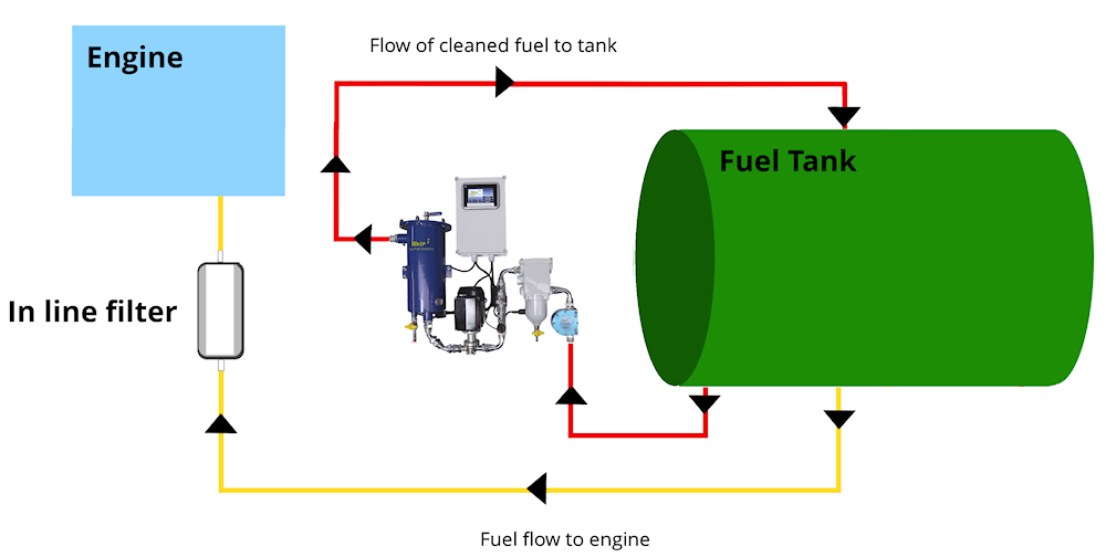
The unit should have unique pipe work from any existing fuel driven equipment. The input to the WASP system should feed from the bottom of the fuel tank (via a ball valve and a foot valve or non return valve)
-
The system should pick-up fuel from the lowest point of the tank at one end, (below the level of the fuel feed to your engine) and ideally return it to the highest point at the opposite end.
- The output should return to the tank at the top, opposite end to the input ideally.
- The unit can be controlled via BMS, however it is capable of self operation and monitoring.
- System must be primed before use and operation. It must also be primed after servicing; although with the aforementioned foot or non return valve installed, priming should only need to be done once after installation.
- With power applied, please ensure the system’s time and date have been correctly set.
- We recommend an internal pipe diameter of 3/4” for the 010 model and 1” for the others; however larger diameters will assist the unit as this reduces the frictional losses. Small diameters, long pipe runs or many bends in the pipe work will cause high frictional losses and cause the system to run slower than its maximum speed, or in extreme cases cause it to stop. Likewise high fuel lifts or fuel heads will also cause the unit to run slower.
-
In any typical fuel tank, the pipe feeding fuel to the engine is not at the bottom, however to successfully clean fuel, the pickup pipe going to the WB unit should be right at the bottom of the tank, below the engine feed.